Other-machine Shop-ice Sphere
\\ moved to etsy site: shop4t3ch.etsy.com
2010.3.15
vise done ... got a self centering 3 jaw auto centering chuck for a lathe with a 'flat back'.
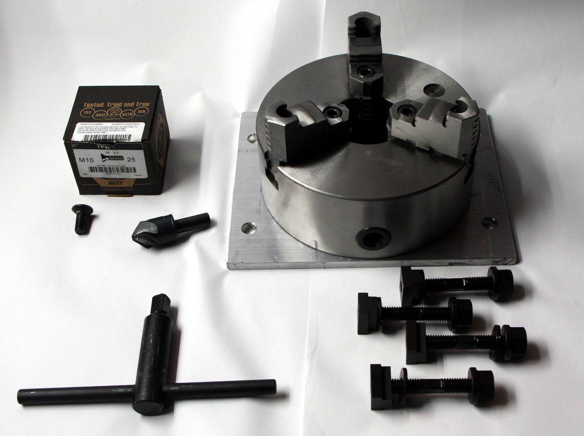
3 jaw chuck mounted on 3/8 plate
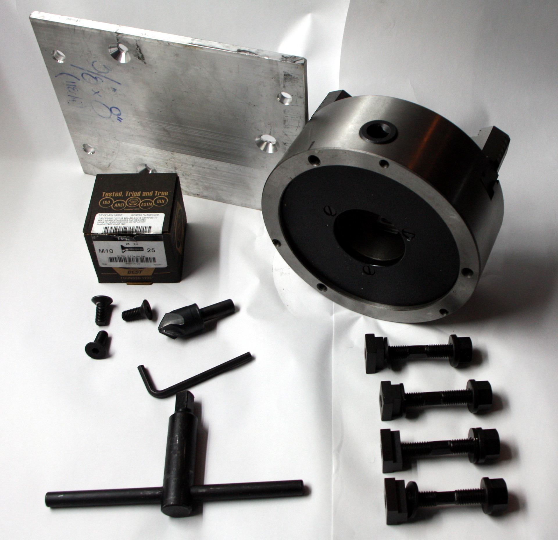
3 jaw chuck with flat bottom
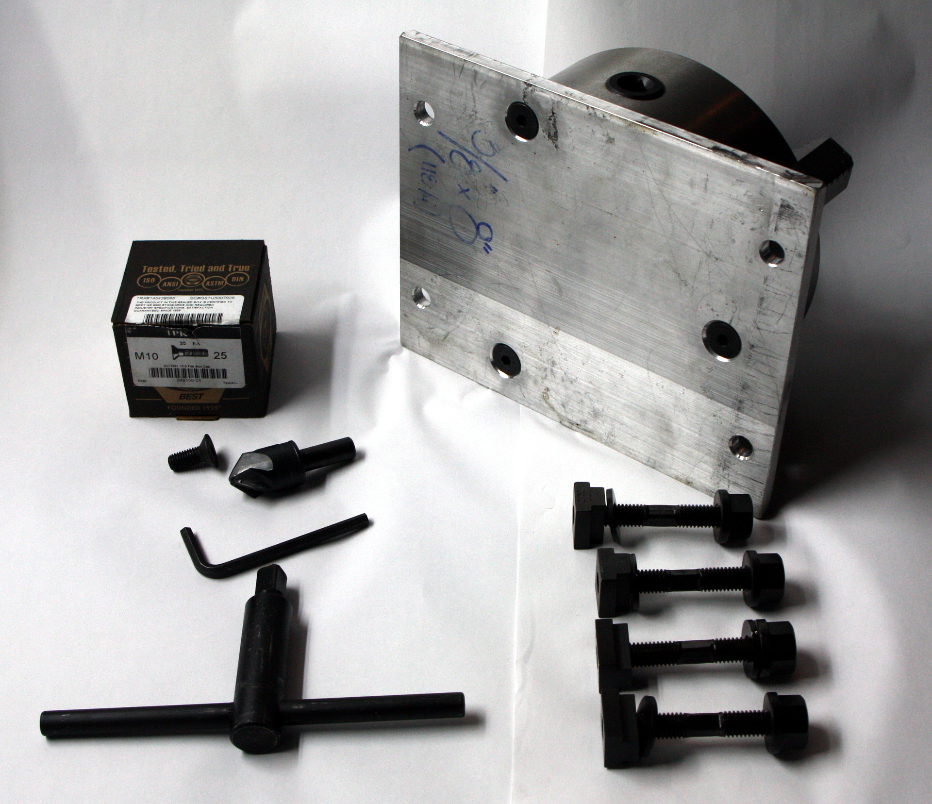
showing plate bottom with chuck mounted
Why 'flat back' ? I didn't want to deal with a lathe mounting bracket. The 3 jaw chucks mounting bolts come from behind the jaws and were 10mm x 1.5 pitch, got 25mm long flat head hex socket bolts. From mcmaster's catalog the spec on the bolts were 20mm head at 90 deg pitch, which told me I needed a 1-inch counter sink with a 90 deg pitch face to match the bolts. It worked quite well.
I got some short 2 inch long 7/16 inch square bar to use as a chuck key when it's mounted to the cnc mill bed as the supplied chuck key will not rotate because it is mounted flush on the mill bed leaving no room for the std key to rotate.
3/8 inch 6061 aluminum plate is 8 inch x 10 inches which fits nicley on the tormac cnc mill's table.
note the plate mounting holes to the table are 5/8 inch to accept std 5/8inch bolts, t-nuts, reg nut and thick cut washers.
The plate to table mounting holes were measured and marked to fit the t-slots on the mill.
2010.3.8
shield done.
3 sheets of lexan 18x24 inches, 0.093 inches thick
Lexan protective film left on for pictures below.
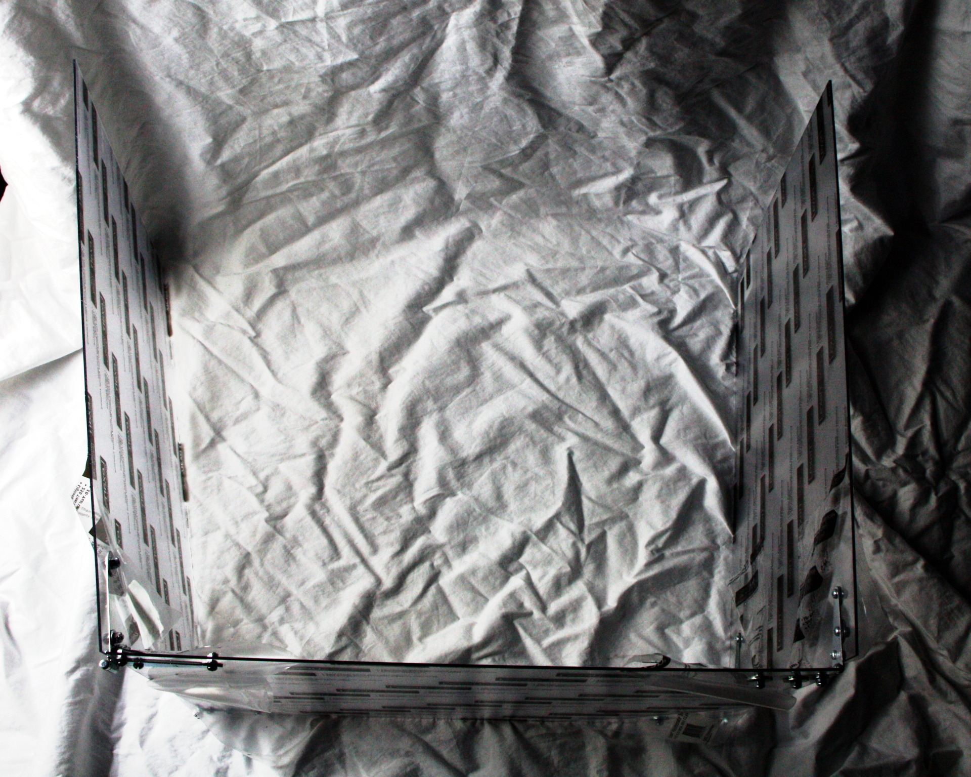
folding fluid shield
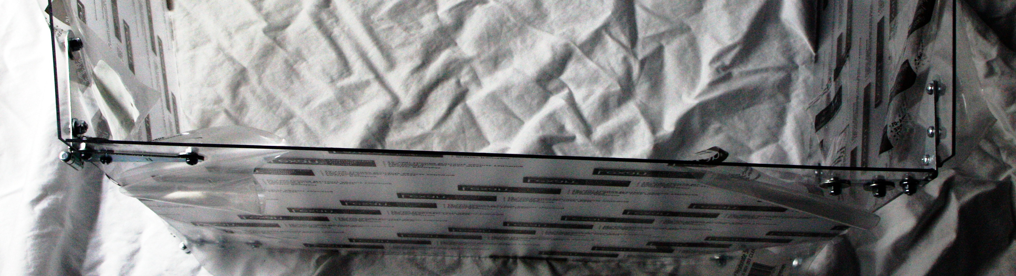
hinges on opposite sides
Picture to the left is from the top. \\I used std 3inch strap hinges that I already had ... they were 2 of one size and 2 slightly different in size.
used 10x24 round head bolts 1/2 inch long with nylon locking nuts.
Picture to the right, note I mounted the hinges on right on the oppisite site of the front shield from the left side .. this is so the finished screen would close somewhat flat for transportation and storage.
See picture in the center/below to see it partially folded.
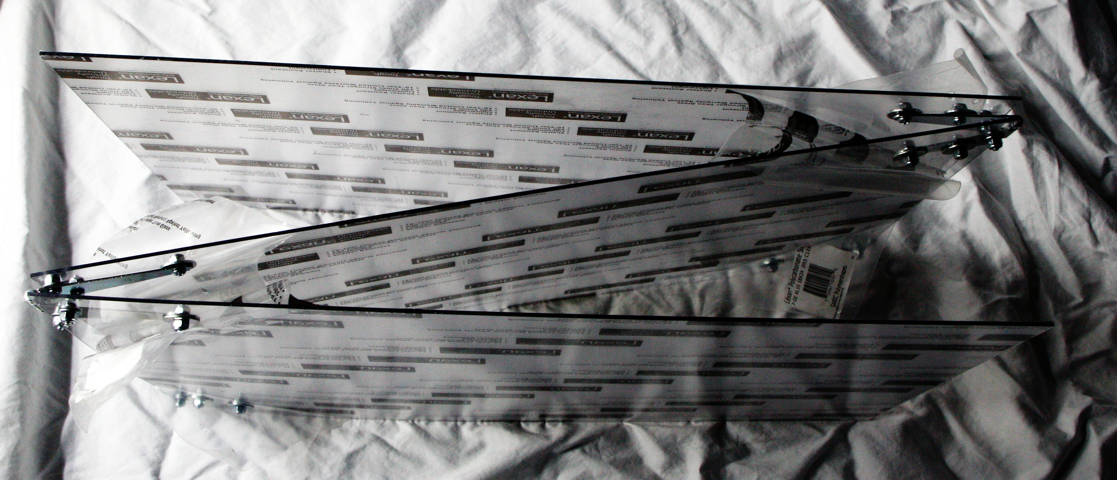
partially folded
4500 rpm here I come ! <grin>
2010.3.7
James suggested an excellent idea on how to make setup on the mill easier, by using a 3 jaw chuck. I like the idea of a self centering vice. I've been offered a cheap 8inch 3 jaw ... now to see if I can mount it to the mill table.
The end mill works very well ... still trying to find the correct feed rate and spindle speed.
Want feed rate of 8ipm to get an acceptable finish time.
Started trying to cut the first 0.562inches in one go ... bad move !
re did the g-code to go 0.1 inch at a time .. better .. but ...
- At 1000rpm the tormac complained when the servos moved the bed ...
- Measured chips and they were about 0.008 inch thick ..
- At 1750 rpm it had less complaints, but still didn't seem correct.
- Measured chips and they were about 0.006 inch but down near the bottom were aprox 0.75 inches long.
- At 4500 rpm it cut like butter (I moved the belt on the pully to get the higher speeds and since the soft ware thought it still was on the lower speed belt settings, the tormac ran at it's highest speed .. 4500rpm).
- At 2500 rpm it was a compromise of tormac servos complaining and it spraying the shop with cutting fluid ! <frown>
I stopped by and got some .125 inch lexan polycarbonate to make a shield to try and keep the fluid near the tormac.
the hemisphere is stepped, but acceptable and much faster at 25mins vs the lathe.
2010.3.5
Going to try milling the hemisphere using concentric circles and a large 1.125inch ball end mill. To do this I need to calculate the diameters of the circles as the cutter descends down into the hemisphere. After thinking about this a little and doing some googling, it turns out that the proof showing that a plane intersecting a sphere is a circle:
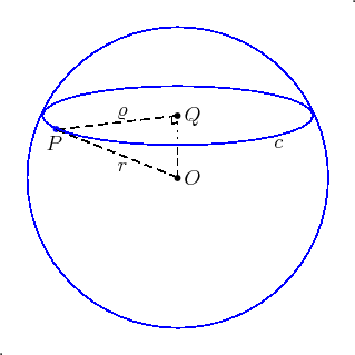
dia of concentric circles
It turns out Pythagorean theorem of right triangles defines the plane that passes through our hemisphere ... nice. In the picture to the left, depending what depth(OQ) from our face the radius(o) of our tools circular path is:
o = (r2 - OQ2)1/2
r is the radius of our hemisphere at its center, ie our face.
note the extents for our use where:
OQ = zero .. this is our face and the cut circle is the same as our hemisphere's radius(r).
OQ = r .. this is our depest point of the hemisphere and our cut circle radius is zero, ie no cut.
2010.3.1
James has setup and produced a beautiful hemisphere using the bridgeport mill angled to the table and using a fly cutter smaller than the diameter of the sphere. The process is a little beyond my capabilities at this point. I think he's going to post a video in operation as I'd like to link to it when he does.
2010.02.21
James and Bill both master machinist introduced me to the concept of cutting the 'half spheres' using a fly cutter and a rotating bed on a mill ... while many hours were spent in their teaching, my mind is not quite able to grasp the mechanics of how this would work ... I applauded their genius, but my simple mind is yet to see how I might be able to actually implement what they suggest ... I'm too concerned with big heavy metal things flying around at what seems like unsafe speeds as it is now, much less the complexity of a fly cutter cutting a hemisphere ... somehow all I envision is loss of limb and life for me and worse for others ... need to think happy thoughts ... need to think happy thoughts ...
2010.02.15
video uploaded to youtube of an ice cube sphere being made ... click the picture to the left to view it.
it shows my clumsy attempt to pick the finished cube up.
I need to get some smaller ice tongs I think.
!!!! 2010.02.14
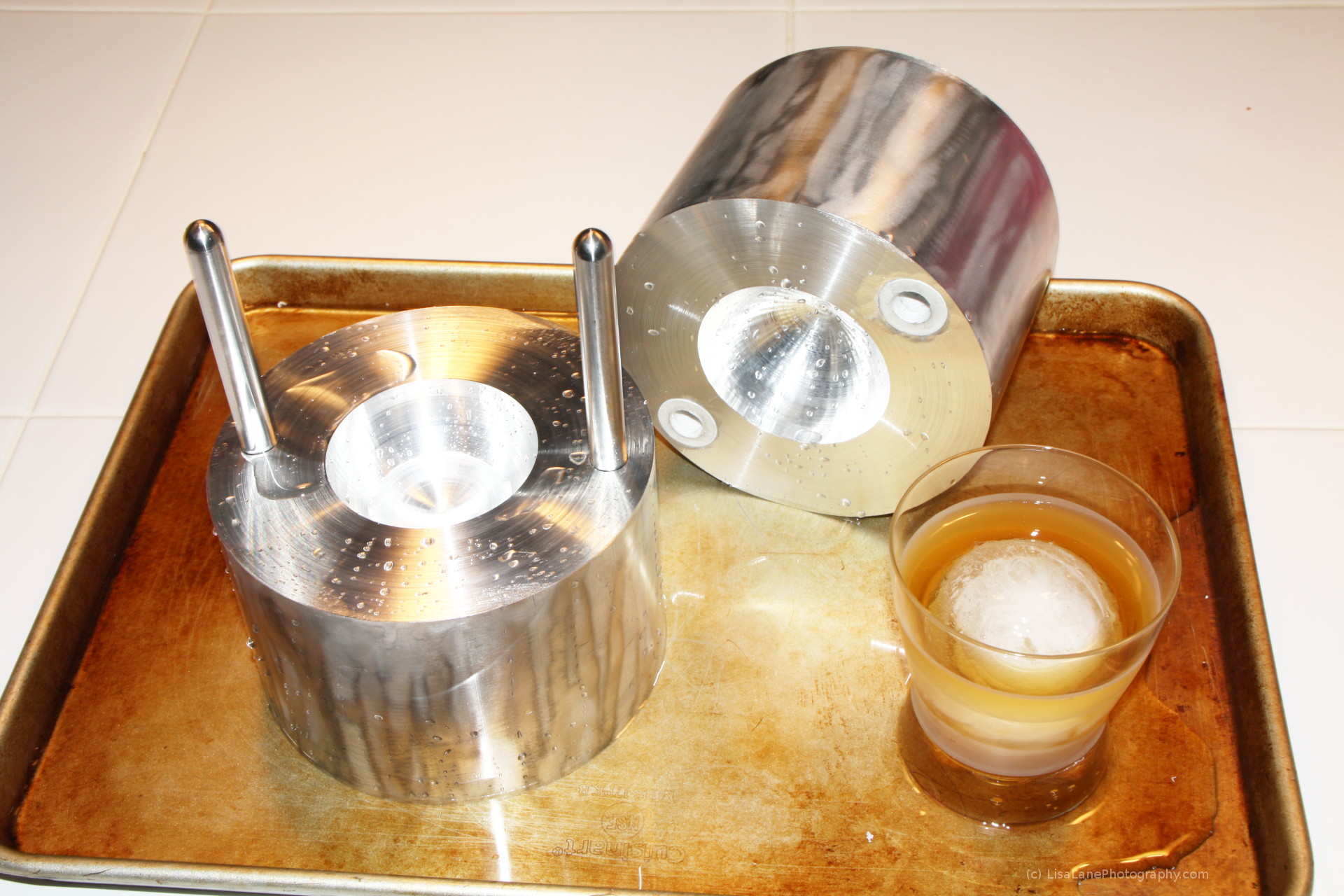
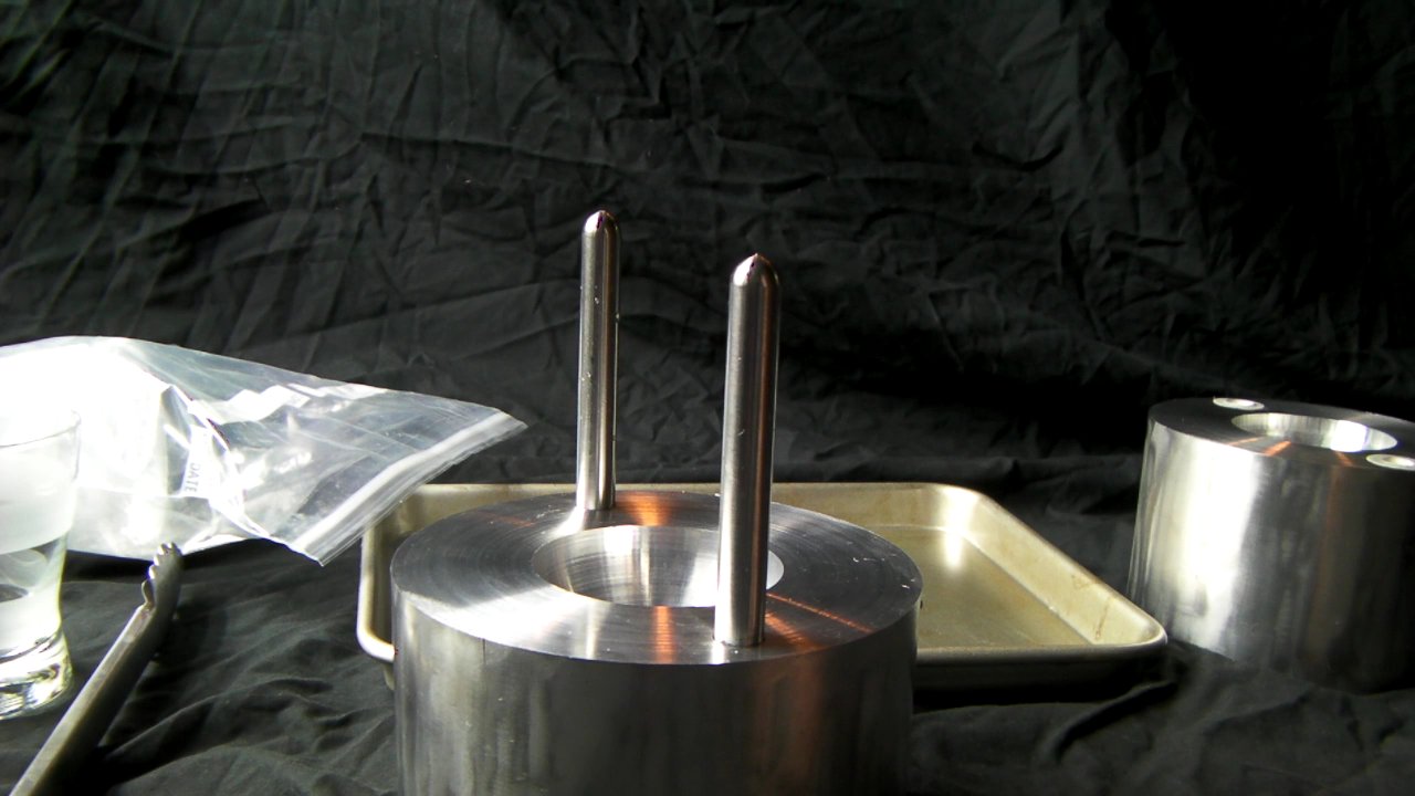
first test and it works great <grin> ! !
this is the 3inch version and it took a huge chunk of ice and made a perfect spherical ice cube in about 90seconds.
the teflon inserts in the top half can be inserted better ie more flush.
the pins in the base had their holes cut with a 3/8 inch by 2.5 inch 4 flute end mill had too much flex at the top of the hole while I was cutting the bottom of the 1.85 inch deep hole. .. about .012 inch too much flex on the .498 inch diameter hole <frown>. The next one I'll try a .5inch drill as it can't be worse <grin>.
heated the 6inch rounds in a toster oven to 450deg for 45mins at the techshop, while the stainless pins and teflon inserts in their freezer for the same amount of time.
worked like a charm.
I had to use a reaming tool to enlarge the teflon inserts .0825 or so .. and it worked great. <grin>
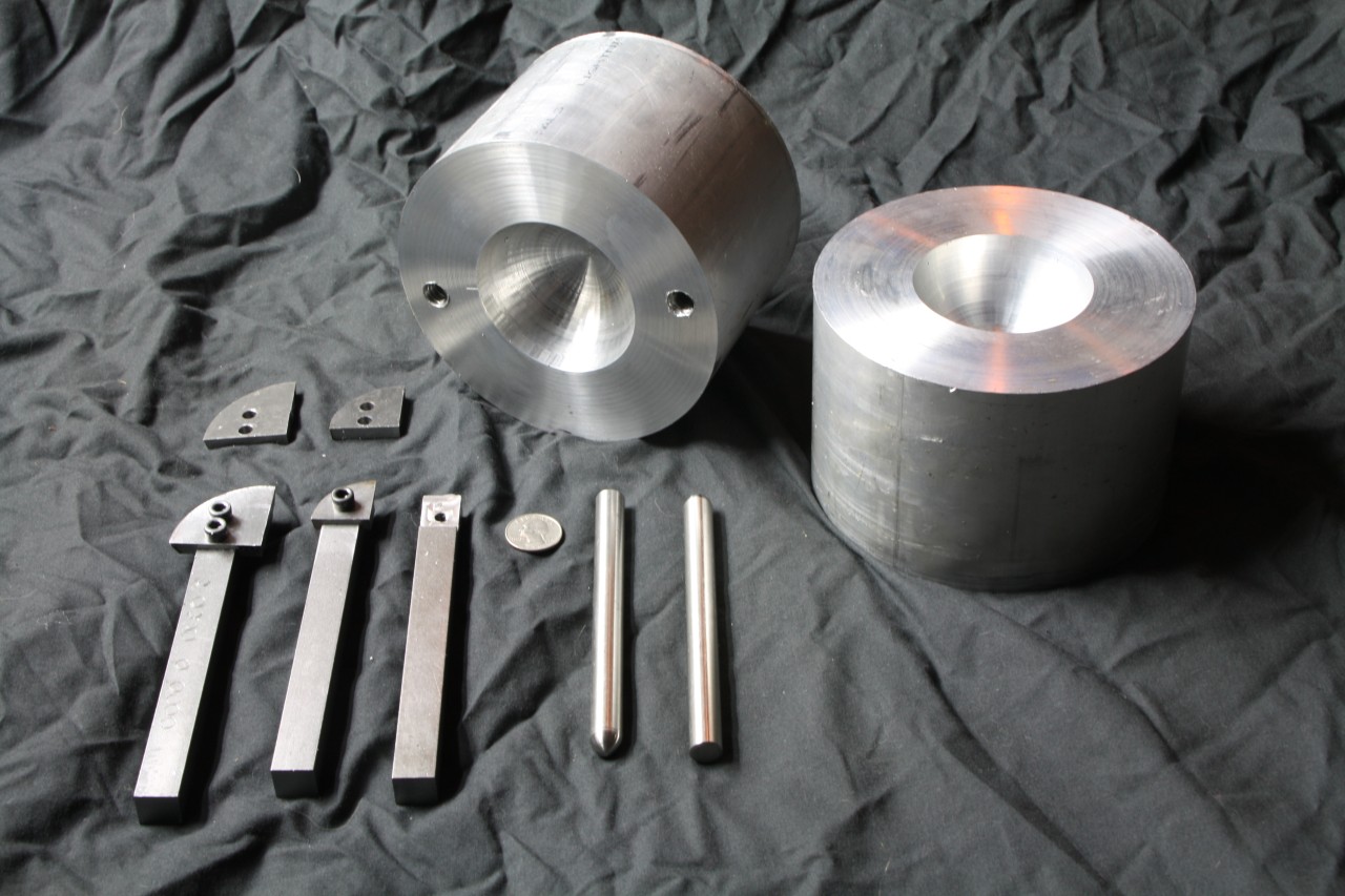
pic of the ice sphere molds so far. in this picture we see the first articles made down at the techshop, with all their great 'big boy toys'. Made btw with the great support and help of abe and the other friendly fine folks down there. Terry's master lathe knowledge saved me days of trying to figure out what I was all ready taught; Roy's patience on trying to teach me what 'sharp' really means.
I couldn't afford a real convex cutter for the lathe and I had my doubts that it could cut a full half a sphere in the aluminum rod.
so ... using 01 tool steel I cut on a tormac cnc mill some quarter round tool heads to dig out the spherical halves need to form the 3inch ice cubes.
after grounding the tool heads and 5/8inch bar to allow for material removal from the 6inch round bar aluminum, ie cut face on the tool head and rotational clearance on the completed tool.
note I plan to make ice molds of 3inches, 2.5inches and 2 inch.
after doing some proof of concepts by hand guiding the two halves together, I think the 3inch spherical ice cubes are preferred.
the 6inch round aluminum was chucked in a metal lathe and using the self made boring tool you see pictured, the boring went slow and very successful ... it took about 30 minutes for each half.
using the tormac cnc mill, I'm having some issues with boring the stainless steel pin holes in the 'bottom' mold. I tried using '3/8inch boring bars' and destroyed 2 of them to make the cr*ppy holes seen in the picture. The holes are meant to be 0.5"-0.002". I just bought a 3/8 x 2inch 4 flute end mill which I hope makes the job easier.
items used
self made spherical / convex / boring tool
to be used on the metal lathe to bore the convex spherical halves in the aluminum 6" rod :
- 5/8" square bar x 5" long, cold rolled mild steel; used for the boring head below.
- 1/4" x 20 x 5/8" long cap head screws; 2 of these for the 3" boring head.
- 1/4" x 20 tab; to thread the 5/8" bar stock to attach the boring head tool.
- #7 drill for threads.
- 3" x 1/4" x 18" 01-die-steel; used to cut the boring head out of.
- 1/4" 4 flute end mill to cut the 01-die-steel to make the boring head tool.
stock and tools used in the molds:
- 6" round bar of 6061 aluminum, 4" long; 2 of these. Weigh about 12 lbs each.
- 1/2" x 5" 316 polished stainless steel round rod for the pins to guide the two mold halves together.
- 3/8" convex radius tool bit for the lathe to round the pin ends that are exposed; 3359A23
- 3/8" x 2" 4 flute end mill used to mill the bushing upper mold half, pin base holes. 8977A491
- 9/16" drill for the pin holes in the upper mold half. silver demming reduced shaft 2933A26
\\
\\
top level subjects: